
INTRODUCTION
The World Meteorological Organization (WMO) code form FM 94 BUFR (Binary Universal Form for the Representation of meteorological data) is a binary code designed to represent, employing a continuous binary stream, any meteorological data. There is, however, nothing uniquely meteorological about BUFR. The meteorological emphasis is the result of the origin of the code. The code form may be applied to any numerical or qualitative data type.
BUFR is the result of a series of informal and formal «expert meetings» and periods of experimental usage by several meteorological data processing centers. The WMO Commission for Basic Systems (CBS) approved BUFR at its January/February 1988 meeting. Changes were introduced at the CBS Working Group on Data Management, Sub-Group on Data Representation meetings in May, 1989 and October 1990. The changes introduced at the October 1990 meeting were of such magnitude that BUFR, Edition 2 was defined, with an effective date of November 7, 1991.
The key to understanding the power of BUFR is the code's self-descriptive nature. A BUFR «message» (or record, the terms are interchangeable in this context) containing observational data of any sort also contains a complete description of what those data are: the description includes identifying the parameter in question, (height, temperature, pressure, latitude, date and time, whatever), the units, any decimal scaling that may have been employed to change the precision from that of the original units, data compression that may have been applied for efficiency, and the number of binary bits used to contain the numeric value of the observation. This data description is all contained in tables which are the major part of the BUFR documentation.
The strength of this self-descriptive feature is in accommodating change. For example, if new observations or observational platforms are developed, there is no need to invent a new code form to represent and transmit the new data; all that is necessary is the publication of additional data description tables. Similarly for the deletion of possibly outdated observations: instead of having to send «missing» indicators for a long period while awaiting a change to a fixed format code, the «missing» data are simply not sent in the message and the data description section is adjusted accordingly. The data description tables are not changed, however, so that archives of old data may be retrieved.
This self-descriptive feature leads to another advantage over character oriented codes — The relative ease of decoding a BUFR message. Where a large number of specialized and complex programs are now needed to decode the plethora of character codes in current use, it is entirely feasible to write a single «universal BUFR decoder» program capable of decoding any BUFR message. It is not a trivial task to write such a BUFR decoder, but once it is done, it is done for all time. The program will not have to change with changes in observational practices; only the tables will need to be augmented, a relatively trivial task.
The development of BUFR has been synonymous with the development of the data description language that is integral to it. Indeed the major portion of the full description of BUFR is a description of the vocabulary and syntax of the data description language. The definition of the data description language, and the «descriptors» that are its vocabulary, are what give BUFR its «universal» aspect: any piece of information can be described in the language, not just meteorological observations.
The other major aspect of BUFR is reflected in the first initial, «B»; BUFR is a purely binary or bit oriented form, thus making it both machine dependent and, at the same time, machine independent. The dependency comes in the construction or interpretation of BUFR messages: there is not much for a human to look at (unless she is very patient) as all the numbers in a message, whether data descriptors or the data themselves, are binary integers. And that, of course, leads to the machine independence: with BUFR consisting entirely of binary integers any brand of machine can handle BUFR as well as any other.
The binary nature of BUFR leads to another advantage over character codes: the ease and speed of converting the message into an internally useful numeric format. With character codes the conversion from ASCII (or EBCDIC) to integer or floating point is expensive relative to the conversion from binary integers to floating point. The latter is all that BUFR requires. In some tests, the European Centre for Medium-Range Weather Forecasts found a speedup of better than 6 times in decoding BUFR messages over the corresponding TEMP (WMO Radiosonde character code FM 35-IX Ext.) messages. The BUFR data also required about half the machine memory as the character data.
All of this does assume the availability of well designed computer programs that are capable of parsing the descriptors, which can be a complex task, matching them to the bit stream of data and extracting the numbers from the stream, responding properly to the arrival of new (or the departure of old) data descriptors, and reformatting the numbers in a way suitable for subsequent calculations. The bit oriented nature of the message also requires the availability of bit transparent communications systems such as the x.25 protocol. Such protocols have various error detecting schemes built in so there need be little concern about the corruption of information in the transmission process.
Dr. John D. Stackpole
NOAA/NWS
National Meteorological Center
Camp Springs, MD 20746 U.S.A.
CHAPTER 1
Sections of a BUFR Message
1.1 Introduction. The term «message» refers to BUFR being used as a data transmission format; however, BUFR can, and is, used in several meteorological data processing centers as an on-line storage format as well as a data archiving format.
1.2 Specifications of Octets Within Each Section. For transmission of data, each BUFR message consists of a continuous binary stream comprising 6 sections.
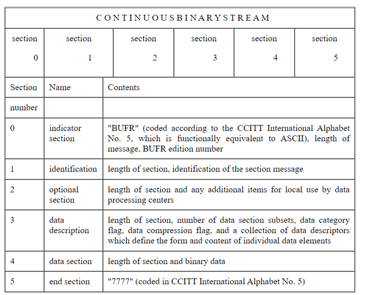
Each of the sections of a BUFR message is made up of a series of octets. The term octet, meaning 8 bits, was coined to avoid having to continually qualify byte as an 8-bit byte. Also, in French, the words «byte» and «bit» are pronounced the same (as «beet»), «octet» clearly avoids that problem, too. An individual section shall always consist of an even number of octets, with extra bits added on and set to zero when necessary. Within each section, octets are numbered 1, 2, 3, etc., starting at the beginning of each section. Bit positions within octets are referred to as bit 1 to bit 8, where bit 1 is the most significant, leftmost, or high order bit. An octet with only bit 8 set would have the integer value 1.
Theoretically there is no upper limit to the size of a BUFR message but, by convention, BUFR messages are restricted to 15000 octets or 120000 bits. This limit is to allow an entire BUFR message to be contained within memory of most computers for decoding. It is also a limit set by the capabilities of the Global Telecommunications System (GTS) of the WMO. The BLOK feature, described elsewhere, can be used to break very long BUFR messages into parts, if necessary.
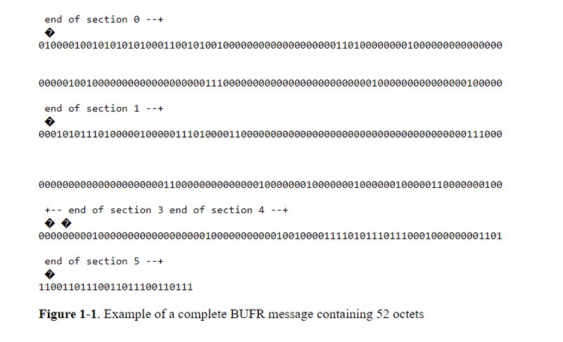
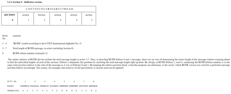
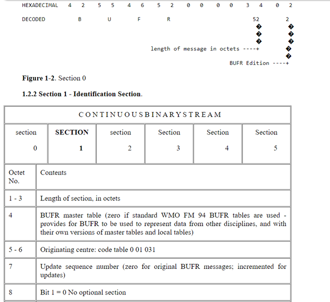
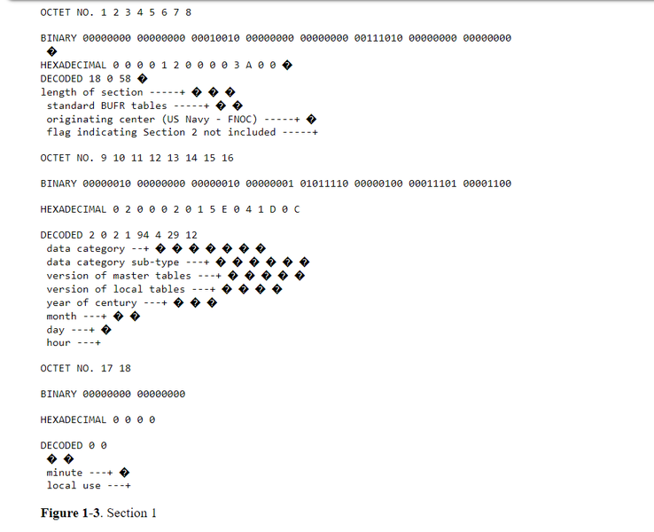
Figure 1-1 is an example of a complete BUFR message containing 52 octets. This particular message contains 1 temperature observation of 295.2 degrees K from WMO block/station 72491. Figures 1-2 through 1-7 illustrate decoding of the individual sections. The spaces between octets in Figures 1-2 through 1-7 were added to improve readability.
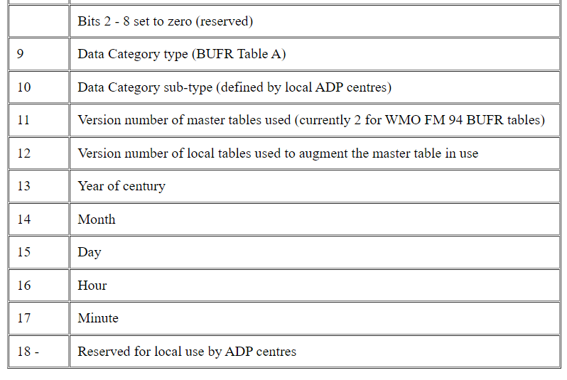
The length of section 1 can vary between BUFR messages. Beginning with Octet 18, a data processing center may add any type of information as they choose. A decoding program may not know what that information may be. Knowing what the length of the section is, as indicated in octets 1-3, a decoder program can skip over the information that begins at octet 18 and position itself at the next section, either section 2, if included, or section 3. Bit 1 of octet 8 indicates if section 2 is included. If there is no information beginning at octet 18, one octet must still be included (set to 0) in order to have an even number of octets within the section.
1.2.3 Section 2 — Optional Section.
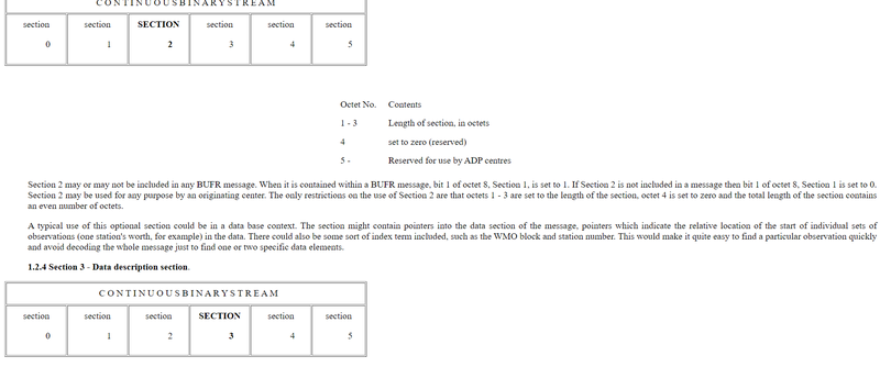
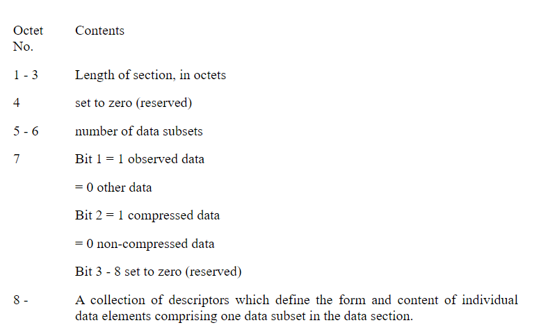
If octets 5-6 indicate that there is more than one data subset in the message, with the total number of the subsets given in those octets, then multiple sets of observations, all with the same format (as described by the data descriptors) will be found in Section 4. This is, for example, a means of building «collectives» of observations. Doing so realizes a large portion of the potential of efficiency in BUFR.
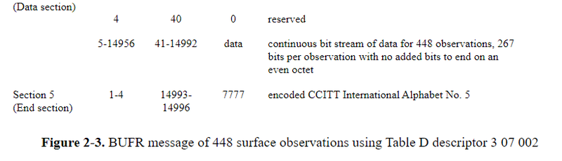
In the flag bits of octet 7, «observed data» is taken to mean just that; «other data», is by custom, if not explicit statement, presumed to be forecast information, or possibly some form of «observation», indirectly derived from «true» observations. The nature of «data compression» will be described in Chapter 4.
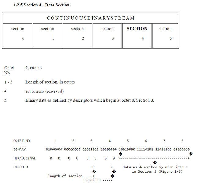
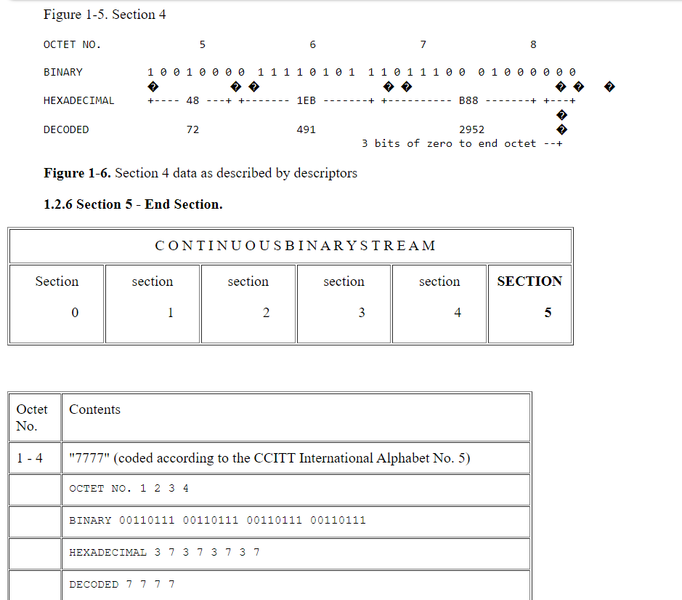
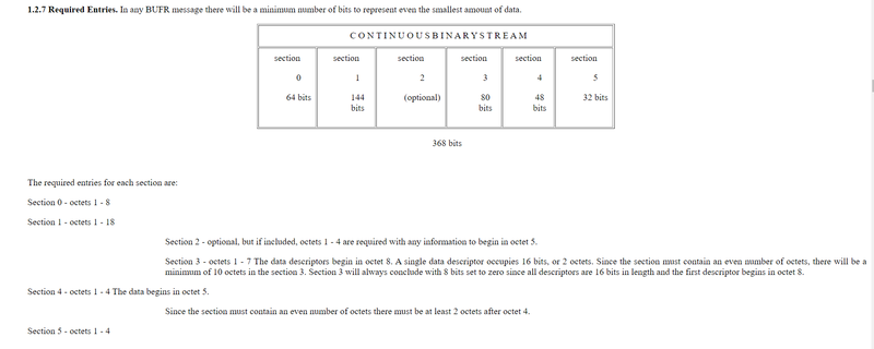
Figure 1-8 is the same BUFR message as in Figures 1-1 to 1-7. The bold areas in Figure 1-8 are those octets which are required in any BUFR message. Not included in the bold areas are descriptors contained in octets 8 — 14 of Section 3 and the data in Octets 5 — 8 of section 4.
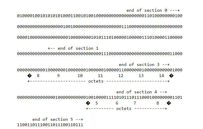
Figure 1-8. Required entries in sample BUFR message
1.2.8 BUFR and Data Management. Sections 3 and 4 of BUFR contain all of the information necessary for defining and representing data. The remaining sections are defined and included purely as aids to data management. Key information within these sections is available from fixed locations relative to the start of each section. It is thus possible to categorize and classify the main attributes of BUFR data without decoding the data description in Section 3, and the data in Section 4.
CHAPTER 2
BUFR Tables
2.1 Introduction . BUFR employs 3 types of tables: BUFR tables, code tables and flag tables.
The tables in BUFR that contain information to describe, classify and define the contents of a BUFR message are called BUFR tables. There are 4 tables defined: Tables A, B, C and D.
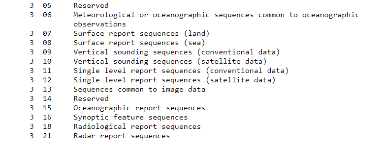
2.2 TABLE A — Data Category. Table A is referred to in Section 1 and provides a quick check for the type of data represented in the message. Of the 256 possible entries for Table A, 17 are currently defined:
Table 2-1. BUFR TABLE A — DATA CATEGORY
Code | |
Figure | Meaning |
0 | Surface data — land |
1 | Surface data — sea |
2 | Vertical soundings (other than satellite) |
3 | Vertical soundings (satellite) |
4 | Single level upper-air data (other than satellite) |
5 | Single level upper-air data (satellite) |
6 | Radar data |
7 | Synoptic data |
8 | Physical/chemical constituents |
9 | Dispersal and transport |
10 | Radiological data |
11 | BUFR tables, complete replacement or update |
12 | Surface data (satellite) |
13-19 | Reserved |
20 | Status information |
21 | Radiances |
22-30 | Reserved |
31 | Oceanographic data |
32-100 | Reserved |
101 | Image data |
102-255 | Reserved |
The setting of one of the code figures for Table A (Table 2-1) in octet 9 of Section 1 is actually redundant. The descriptors used in Section 3 of a message define the data in Section 4, regardless of the Table A code figure. Decoding programs may well reference Table A, finding it useful to have a general classification of the data available prior to actually decoding the information and passing it on to some subsequent application program.
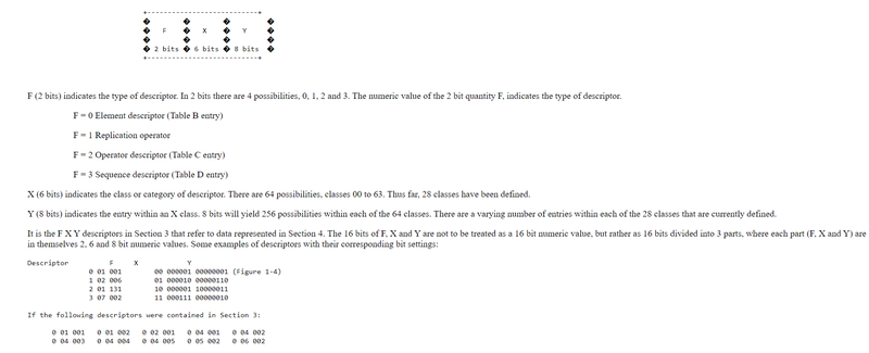
2.3 TABLE B — Classification of Elements. Table B is referenced in Section 3 of a BUFR message and contains descriptions of parameters encoded in Section 4. Table B entries, as described in the WMO Manual On Codes, Volume 1, Part B, consist of 6 entities:
a descriptor consisting of the 3 parts F, X and Y
element name
units: basic (SI) units for the element
scale: factor (equal to 10 to the power [scale]) by which the element has been multiplied prior to encoding
reference value: a number to be subtracted from the element, after scaling, (if any), and prior to encoding
data width, in bits, the element requires for representation in Section 4
A Table B descriptor consists of 16 bits (2 octets) divided into 3 parts, F, X and Y.
The element name is a plain language description of the element entry of the table.
The units of Table B entries refer to the format of how the data in Section 4 is represented. The data may be numeric as in the case of a WMO block number, character data as in the case of an aircraft identifier. When data is in character form, the character representation is always according to the CCITT International Alphabet No. 5. The units may also refer to a code or flag table, where the code or flag table is described in the WMO Manual On Codes using as the code or flag table number the same number as the F X Y descriptor. Other units are in Standard International (SI) units, such as meters or degrees Kelvin.
The scale refers to the power of 10 that the element in Section 4 has been multiplied by in order to retain the desired precision in the transmitted data. For example, the units of latitude are whole degrees in Table B. But this is not precise enough for most usages, therefore the elements are to be multiplied by 100 (102) so that the transmitted precision will be centidegrees, a more useful precision. On the other hand, the (SI) unit of pressure in Table B is Pascals, a rather small unit that would result in unnecessarily precise numbers being transmitted. The BUFR Table B calls for pressure to be divided by 10 (10-1) resulting in a transmitted unit of 10ths of hPa, or tenths of millibars, a more reasonable precision for meteorological usage. These precisions can be changed on the fly, so to speak, if the table values are not appropriate in special cases. This is done through the use of «operator descriptors» — see below, 2.4 Table C.
The reference value is a value that is to be subtracted from the data after multiplication by the scale factor, if any, before encoding into Section 4 in order to produce, in all cases, a positive value. In the case of latitude and longitude, south latitude and west longitude are negative before applying the reference value. If, for example, a position of 35.50 degrees south latitude were being encoded, multiplying -35.50 by 100 (scale of 2) would produce -3550. Subtracting the reference value -9000 would give 5450 that would be encoded in Section 4. To obtain the original value in decoding Section 4, adding back the -9000 reference value to 5450 would result in -3550, then dividing by the scale (100) would obtain -35.50.
The data width of Table B entries is a count of how many bits the largest possible value of an individual data item of Section 4 occupies.
In those instances where a Table B descriptor defines an element of data in Section 4, where that element is missing for a given subset, then all bits for that element will be set to 1's in Section 4.
Obviously, without an up-to-date Table B, a decoder program would not be able to determine the form or content of data appearing in Section 4.
2.3.1 Data Replication. A special descriptor called the replication operator (F = 1) is used to define a range of subsequent descriptors, together with a replication factor. This enables the appropriate descriptors to be considered to be repeated a number of times. In general for data replication, X indicates the number of immediately following descriptors that are to be replicated as a repeated set, and Y indicates the total number of replications. This, of course, implies, that the same pattern will be found in Section 4, the data section. This ability to describe a repeated pattern in the data by a single set of descriptors contributes to the efficiency of BUFR.
As an example, imagine the following sequence appears in Section 3:
1 02 006 0 07 004 0 01 003
the meaning of 1 02 006 is that the next 2 descriptors are repeated 6 times, or the equivalent set of descriptors:
0 07 004 0 01 003 0 07 004 0 01 003 0 07 004 0 01 003
0 07 004 0 01 003 0 07 004 0 01 003 0 07 004 0 01 003
A special form of the replication operator allows the replication factor to be stored with the data in Section 4, rather than with the descriptor in Section 3. This special form is called delayed replication. It is indicated by Y = 0. It allows the data to be described in a general way, with the number of replications being different from subset to subset. Since the data now contains an additional data element, the actual replication count, a descriptor must be added to Section 3 to account for, and describe, this (special) data element. The appropriate descriptor is found in Class 31. Special note: the 0 31 YYY (delayed replication factor) descriptor follows immediately after the 1 X 000 (delayed replication) descriptor but is NOT included in the count (X) of the following descriptors to be replicated.
Another form of delayed replication enables both the data description and the corresponding data item or items to be repeated. Entries in Class 31 of Table B are used in association with the delayed replication operator to enable this to be done.
2.4 Table C — Data Description Operators. Table C data description operators (Chapter 5) are used when there is a need to redefine Table B attributes temporarily, such as the need to change data width, scale or reference value of a Table B entry. Table C is also used to add associated fields such as quality control information, indicate characters as data items, and signify data width of local descriptors.
Any BUFR message may be encoded without using Table D. The data description contained within Section 3 can be accomplished entirely by using only element descriptors of Table B and operator descriptors of Table C. To do so, however would involve considerable overhead in terms of the length of the Section 3 data description. The use of Table D is another major contributor to the efficiency of BUFR.
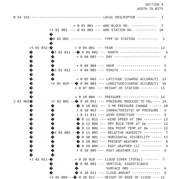
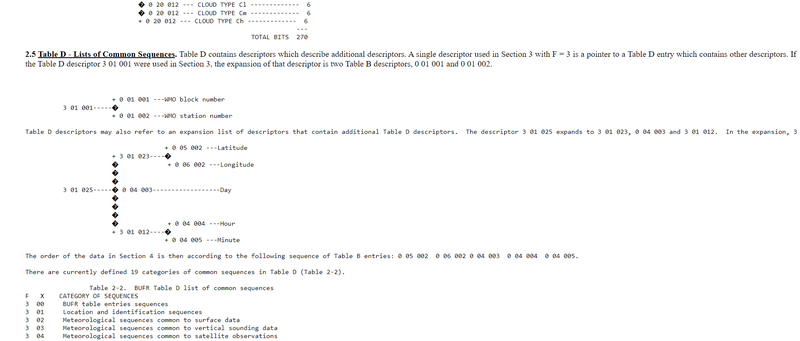
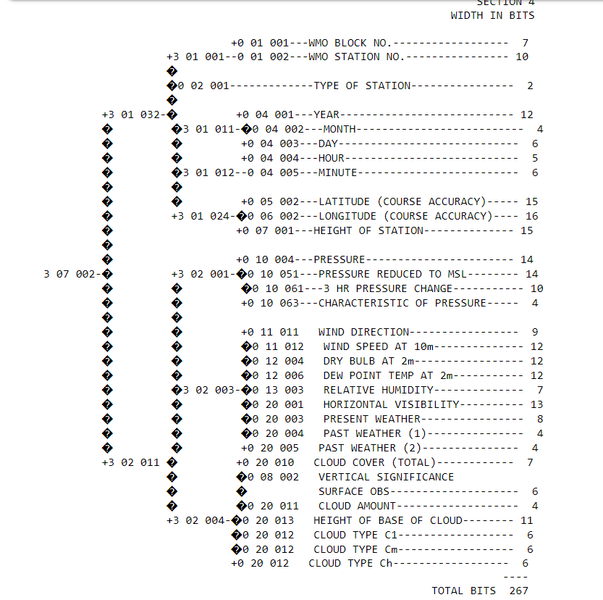
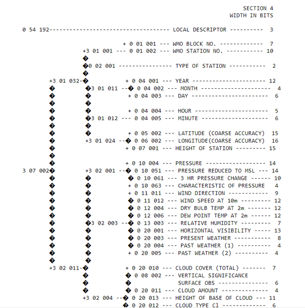
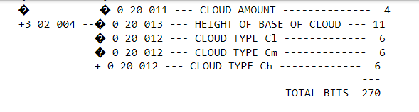
2.6 Message Layout. Figure 2-1 illustrates how the single descriptor 3 07 002 expands into 2 more Table D descriptors, 3 01 032 and 3 02 011. The descriptor 3 01 032 further expands into 5 more descriptors 3 01 001, 0 02 001, 3 01 011, 3 01 012 and 3 01 024. As is shown in Figure 2-1, descriptors in Table D may themselves refer to Table D, provided no circularity results on repeated expansion. Completion of the expansion process leads to a total of 31 Table B descriptors. The 16 bits in Section 3 taken by the descriptor 3 07 002 results in a savings of 480 bits (30 x 16 bits) over what the 31 Table B descriptors would occupy in bits.
Table D has been limited to lists of descriptors likely to be most frequently used. Table D was not designed to be comprehensive of all sequences likely to be encountered. To do so would require an excessively large Table D and would reduce considerably flexibility when encoding minor differences in reporting practices. More flexibility is retained if the Data Description Section contains several descriptors.
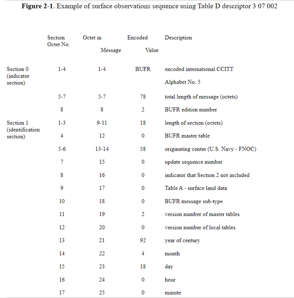
A complete layout of a BUFR message containing just 1 surface observation is illustrated in Figure 2-2. As indicated in octets 5-7 of Section 1, there are a total of 78 octets in the message, or 624 bits. Of the 624 bits, 267 are for the actual parameters of data (Figure 2-1) and the remaining 357 bits are BUFR overhead. BUFR overhead in this context is the number of bits that are not actual surface data. In this example there are more bits used for the overhead than for the surface data.
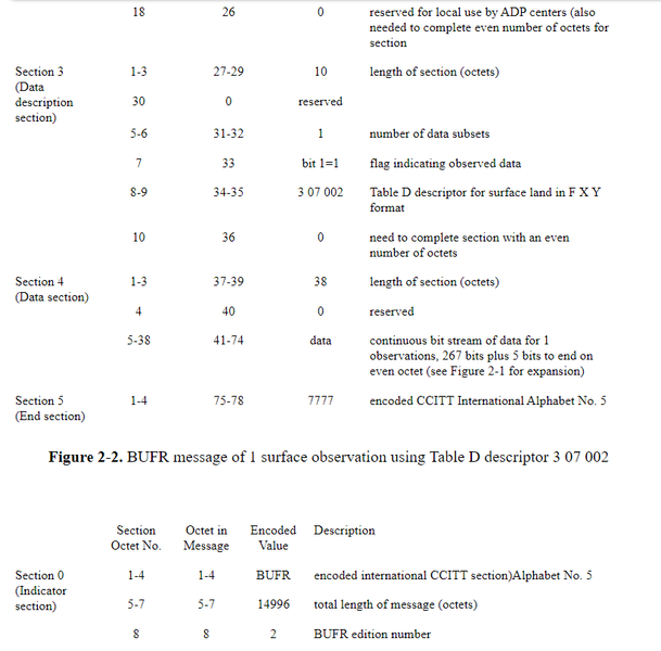
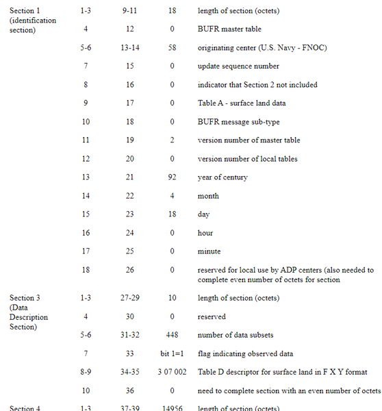
Figure 2-3 is a complete layout of a BUFR message containing the maximum number of 448 subsets to fit within the 15000 octet limit. This message would contain 14996 octets or 119968 bits. Of these 119968 bits, 119616 are data and 352 bits are BUFR overhead. The 5 bit difference in overhead from Figure 2-2 (357 bits) and Figure 2-3 (352 bits) is due to the number of bits set to 0 at the end of Section 4 in order to complete the section at the end of an even numbered octet. For 1 subset of 267 bits, 5 additional bits are needed to complete the octet. For 448 subsets, or 119616 bits, no additional bits are needed to complete the last octet.
2.6.1 Comparison of BUFR and Character Code Bit Counts. The surface observations illustrated in Figures 2-1 to 2-3 are the equivalent of the following parameters in the WMO code form FM 12-IX Ext. SYNOP:
YYGGiw IIiii iRixhVV Nddff 1snTTT 2snTdTdTd 3PoPoPoPo
4PPPP 5appp 7wwW1W2 8NhCLCMCH
Data encoded in this form would consist of 55 characters plus 10 spaces between each group of 5 characters for a total of 65 characters. For transmission purposes these 65 characters would require a total number of 520 bits (65 X 8 bits per character). A complete BUFR message with 1 observation (Figure 2-2) requires 78 octets or 624 bits, 104 more than the corresponding character representation. Of these 624 bits, 267 are taken by the surface observation and 357 as BUFR overhead. If, however, 448 observations in character form were transmitted, the total number of bits would be 232960 (520 X 448). The corresponding BUFR representation (Figure 2-3) would require 14996 octets, or 119968 bits, a savings of 112992 bits over the character representation. The 112992 bits is equivalent to 217 observations in character form or 423 observations in BUFR, not counting the BUFR overhead. While these numbers may be viewed in different ways, the real significance is that BUFR is far more efficient, in terms of number of bits to represent a meteorological observation, than character forms.
2.7 Code Tables and Flag Tables. Since some meteorological parameters are qualitative or semi-qualitative, they are best represented with reference to a code table.
2.7.1 Code Tables. BUFR code tables and flag tables refer to elements defined within BUFR Table B. They are numbered according to the X and Y values of the corresponding Table B reference. For example, the Table B entry 0 01 003, WMO Region number, geographical area, indicates in the Unit column that this is a BUFR code table, the number of that code table being 0 01 003.
Many of the code tables that have been included in the BUFR specification are similar to existing WMO code tables for representing character data. Attachment II of the WMO Manual on Codes, Volume 1, Part B is a list of the code tables associated with BUFR Table B and the existing specifications and code tables of the WMO Manual on Codes, Volume 1, Part A.
There is not a one-to-one BUFR code table relationship to the character code tables. The character Code Table 3333, Quadrant of the Globe, for example, has no meaning in BUFR, as all points on the globe in BUFR are completely expressed as latitude and longitude values.
2.7.2 Flag tables. In a flag table, each bit indicates an item of significance. A bit set to 1 indicates an item is included, or is true, while a bit set to 0 indicates omission, or false. In any flag table, when all bits are set it is an indication of a missing value. Flag tables additionally enable combinations to be identified. In all flag tables within the BUFR specification, bits are numbered from 1 to N from most significant to least significant within a data width of N bits, i.e., from left (bit 1) to right (bit N).
2.7.3 Flags. Flags, without reference to a flag table, are also used within Sections 1 and 3 of a BUFR message. In Section 1, octet 8, if bit 1 = 0 this is an indication that the optional section 2 is not contained within the message. If bit 1 = 1, then Section 2 is included.
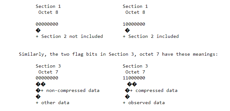
2.8 Local Tables. Since a data processing center may need to represent data conforming to a local requirement, and this data is not defined within Table B, specific areas of Table B and D are reserved for local use (Figure 2-4). These areas are defined as entries 192 to 255 inclusive of all classes. Centers defining classes or categories for local use should restrict their use to the range 48 to 63 inclusive.
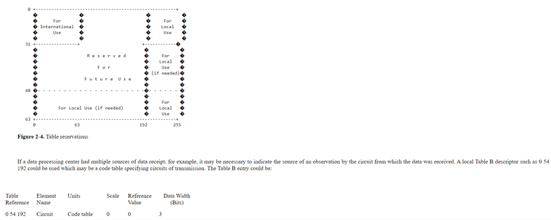
The corresponding local code table could be:
0 54 192
Circuit designators for data receipt
code figure circuit
0 GTS
1 AWN
2 AUTODIN
3 ANTARCTIC
4-7 Reserved
Using the same Table D descriptor, 3 07 002, as in Figure 2-1, adding the local descriptor 0 54 192 would produce the expansion as in Figure 2-5. The following modifications would have to be made to the BUFR message if the local descriptor 0 54 192 were to be included in a message (Figure 2-6):
Section 0, octets 5-7, the total length of the message, increases from 14996 octets to 14998 octets.
Section 1, octet no. 12 (octet 20 within the message) would have the version number of the local tables in use.
Section 3, octets 1-3, the encoded value would increase from 10 octets to 12 octets. If one descriptor were being added, the length of the section increases by 2 in order to keep the section an even number of octets. Octets 5-6, number of data subsets decreases from 448 to 443. The number of data subsets have been reduced to keep the total message length under the 15000 octet maximum.
Also in Section 3, the descriptors will occupy octets 8-11 vice octets 8-9 to accommodate the added descriptor.
Note that in Section 4, octets 1-3, the encoded value for length of section remains the same at 14956 octets. The number of bits needed for 448 subsets without a local descriptor is 119616 (448 X 267), or exactly 14952 octets. For 443 subsets with 3 bits added to each subset for the local information, 119610 bits are needed (443 X 270). Adding 6 bits to complete the octet brings the total bit count for all 443 subsets to 119616, the same number of bits as 448 subsets without the added local information.
Figure 2-5. Example of surface observations sequence using Table D descriptor 3 07 002 and local descriptor
Section Octet No. | Octet in Message | Encoded Value | Description | |
Section 0 (indicator section) | 1-4 | 1-4 | BUFR | Encoded international CCITT |
Alphabet No. 5 | ||||
5-7 | 5-7 | 14998 | total length of message (octets) | |
8 | 8 | 2 | BUFR edition number | |
Section 1 (identification section) | 1-3 | 9-11 | 18 | length of section (octets) |
4 | 12 | 0 | BUFR master table | |
5-6 | 13-14 | 58 | originating center (U.S. Navy — FNOC) | |
7 | 15 | 0 | update sequence number | |
8 | 16 | 0 | indicator that Section 2 not included | |
9 | 17 | 0 | Table A — surface land data | |
10 | 18 | 0 | BUFR message sub-type | |
11 | 19 | 2 | version number of master tables | |
12 | 20 | 1 | version number of local tables | |
13 | 21 | 92 | year of century | |
14 | 22 | 4 | month | |
15 | 23 | 18 | day | |
16 | 24 | 0 | hour | |
17 | 25 | 0 | minute | |
18 | 26 | 0 | reserved for local use by ADP centers (also need to complete even number of octets for Section 3 | |
Section 3 | 1-3 | 27-29 | 12 | length of section (octets) |
4 | 30 | 0 | reserved | |
5-6 | 31-32 | 443 | number of data subsets | |
7 | 33 | BIT 1=1 | flag indicating observed data | |
8-11 | 34-37 | 0 54 192 | local and Table D descriptors | |
3 07 002 | in F X Y format | |||
10 | 38 | 0 | need to complete section with an even number of octets | |
Section 4 | 1-3 | 39-41 | 14956 | length of section (octets) |
4 | 42 | 0 | reserved | |
5-14956 | 43-14994 | data | continuous bit stream of data for 443 observations, 270 bits per observation plus 6 bits to end on even octet | |
Section 5 | 1-4 | 14995- | 7777 | encoded CCITT international Alphabet No. 5 |
Figure 2-6. BUFR message of 443 surface observations using 2 descriptors, local descriptor 0 54 192 and Table B descriptor 3 07 002.
CHAPTER 3
Using Data Replication
3.1 Introduction. When encoding a series of parameters a fixed number of times for all reports represented in Section 4, it may be possible to choose from one of several methods for using Section 3 descriptors.
3.2 Data Replication Examples. If there were 4 elements of cloud information that were described by the Table B descriptors 0 08 002 0 20 011 0 20 012 0 20 013, and these elements were to be repeated 4 times, these 16 total elements of data in Section 4 may be described in the following ways:
1. long and cumbersome method — each element described individually
0 08 002 0 20 011 0 20 012 0 20 013
0 08 002 0 20 011 0 20 012 0 20 013
0 08 002 0 20 011 0 20 012 0 20 013
0 08 002 0 20 011 0 20 012 0 20 013
2. using the replication operator —
1 04 004 0 08 002 0 20 011 0 20 012 0 20 013
The meaning of the descriptor 1 04 004 is that the F portion (1) is indicating this is a replication operator, the X portion (04) means the following 4 descriptors are to be repeated Y (004) times.
3. combine replication operator and Table D descriptor
1 01 004 3 02 005
In this particular example of Table B descriptors there is defined a Table D descriptor 3 02 005 which expands to the 4 descriptors
0 08 002 0 20 011 0 20 012 0 20 013.
The replication operator 1 01 004 followed by 3 02 005 means the data in Section 4, defined by the Table D descriptor 3 02 005, is repeated 4 times.
Using either a replication operator followed by a Table B descriptor or a replication operator followed by a Table D descriptor, if it exists, produces the same definition of data as repeating Table B descriptors. Note, in example 3, that the count of the number of descriptors to be replicated (X, 01) applies to the single Table D descriptor that is actually in the message, and NOT to the set of possibly very many descriptors that the single type 3 descriptor represents.
A special form of the replication operator allows the replication factor to be stored with the data in Section 4, rather than with the descriptor in Section 3. This is particularly useful when describing data such as TEMP or BATHY observations where the number of levels differs from observation to observation. The delayed replication operator is of the form F X Y where F = 1, X indicates how many descriptors are to be replicated, and Y = 000. This operator is to be followed by a Table B descriptor from Class 31. The Class 31 descriptor is not included in the count (X) of the number of following descriptors to be replicated. Thus, if the following sequence of descriptors appeared in Section 3: 1 01 000 0 31 001 0 03 014, the meaning of these descriptors is:
1 01 000 | F = 1 | replication operator |
X = 01 | 1 descriptor is replicated, not counting, i.e. skipping over, the 0 31 001 descriptor | |
Y = 000 | delayed replication | |
0 31 001 | F = 0 | Table B descriptor |
X = 31 | Class 31 — data description operator qualifiers | |
Y = 001 | delayed descriptor replication factor occupying 8 bits in Section 4 (Table B, Class 31 definition) | |
3 03 014 | F = 3 | Table D descriptor |
X = 03 | Category 03 — meteorological sequences common to vertical sounding data | |
Y = 014 | entry 14 of Category 03 |
The Table D descriptor 3 03 014 expands into seven descriptors. The Section 4 data width for the expansion of 3 03 014 is 83 bits.
For each observation encoded into Section 4 the 8 bits preceding the pressure data indicates how many times the following 7 elements are replicated.
Figure 3-1 is an example of TEMP observations sequence using a single Table D descriptor which expands to include delayed replication. In this example, the replication factor indicates how many levels are contained within the observation. The bit count of 245 bits is for 1 level, each additional level would require 83 bits.
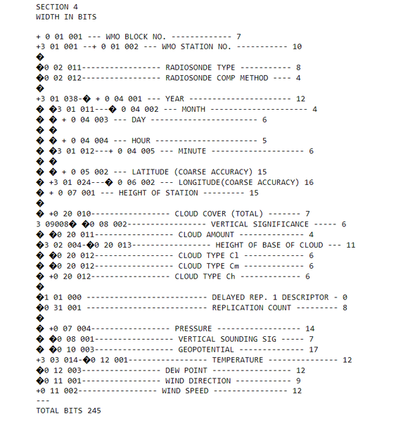
Image Upload
Add image